Description of the Convective Head Engine (CHE) #
Convection in Water (Incompressible Fluid) v Convection in Air (Compressible Fluid)
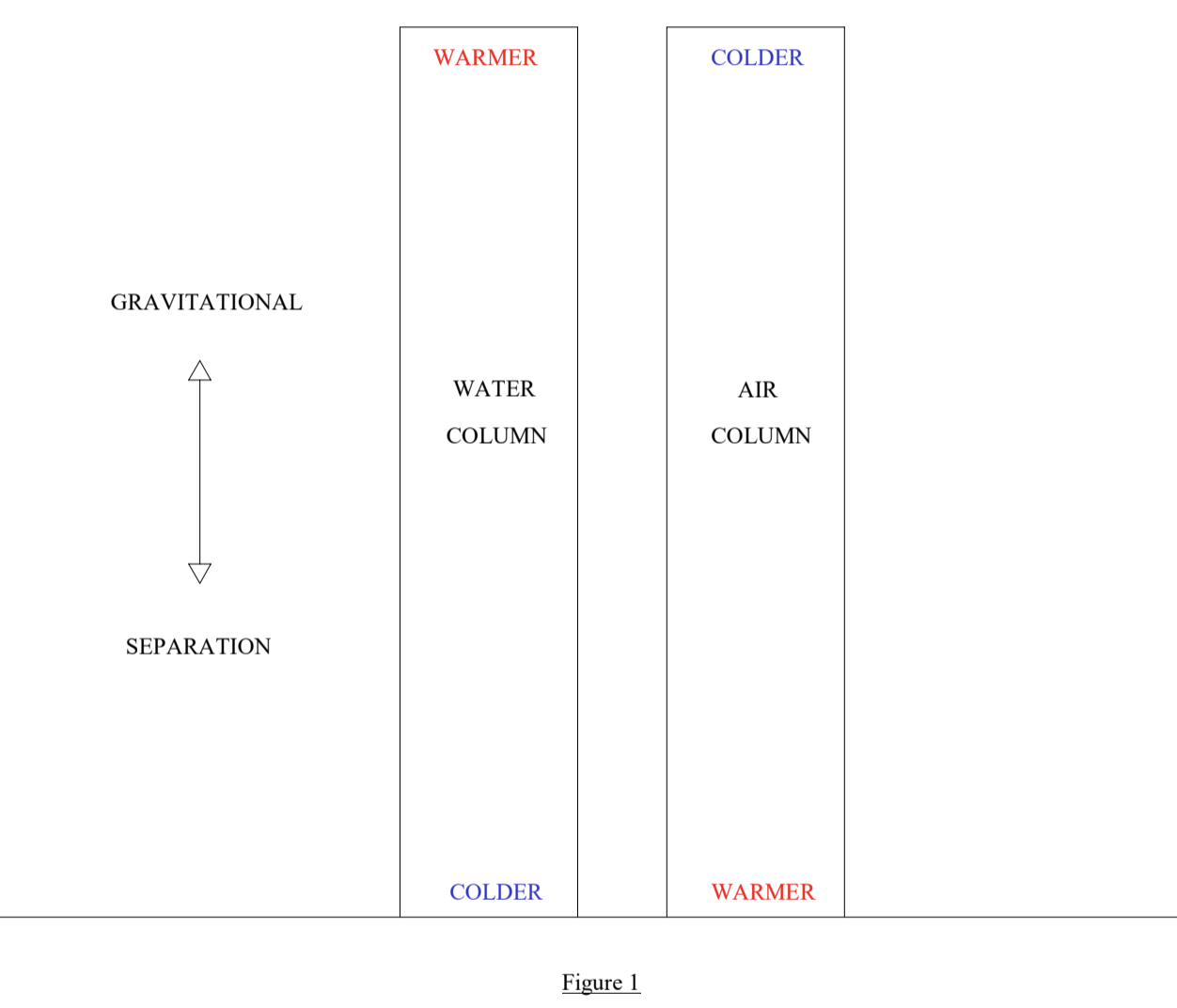
A vertical column of water instantiated in the atmosphere thermally separates in the opposite direction to the atmosphere. Buoyancy forces result in the warmest water rising to the top of the column and coldest sinking to the bottom, whereas the atmosphere has the warmest air at the surface and coldest air at altitude. The fact that air is compressible means that it expands as it rises, and with expansion comes cooling in accordance with the gas laws. This phenomenon is known as the Atmospheric Lapse Rate (see Appendix II). Refer to Fig. 1
Two columns of water in the atmosphere, joined top and bottom with heat exchangers (HX) that allow for heat transfer from the warm water to the relatively cooler air at the top and from the warmer air to the cooler water at the bottom will establish a self-sustaining thermo-siphon flow in the hydraulic circuit. This operates on the same principle as pump-less solar hot water systems with thermo-siphon. Warm water is more buoyant than cold water and rises, and conversely the less buoyant cold water sinks – this sinking/rising of cool/warm water in the opposite legs of the circuit drives the auto-circulation. This is depicted in Fig. 2. At large scale, under standard atmospheric conditions, this flow may be slower than desired, but low grade(up to say 50°C) geothermal heat can be added the hydraulic circuit to speed up the flow rate as well as overcome frictional drag in the HXs. This additional heat will add extra energy for convective uplift, which can be moderated by reducing the Convective Volume (see below).
The Innovative Step #
Use the hydraulic circuit in Fig. 2 to transport heat vertically in successive Convective Uplift Towers (CUT) as indicated in Fig. 3.
Note that the cold conditions at the top heat exchanger (HXT) of the preceding CUT is transferred by thermo-siphon to the base of the next CUT, cooling the surface air entering the base of that CUT via the bottom heat exchanger (HXB). This cooled air has negative buoyancy, but it is drawn up the CUT by the positive buoyancy of the warmed air above its HXT. This is achieved by ensuring that the volume of the warmed section of the CUT is sufficiently large such that there is net positive buoyancy in the entire CUT. This means that the cooled air entering the base of this CUT is cooled further as it is drawn upward towards the HXT. In this way each successive CUT has colder air rising upwards in the space between the HXs. Let us call this air volume- the air on which work is being performed - the Load Volume (LV). The volume of air above the HXT is called the Convective Volume (CV). The volume/buoyancy of the LV is determined by, amongst other factors, the distance between the HXT and HXB as well as the temperature of the air drawn into the bottom of the CUT (see Appendix III for sample calculation). The volume / buoyancy of the Convective Volume is then designed such that the Convective Heat Engine can lift Load Volume air at the rate desired to achieve a certain outcome in potential energy / condensate production. [The physics of this is covered in Appendix II (Section A – Thermals, specifically the Atmospheric Lapse Rate) and demonstrated in the Case Study calculations of Appendix III]
For larger scale developments the series linked CUTs described above can be expanded into groups of parallel-connected CUTs operating at the same temperatures which are connected in series to colder / warmer groups of CUTs downstream and upstream as relevant – see Fig. 4.
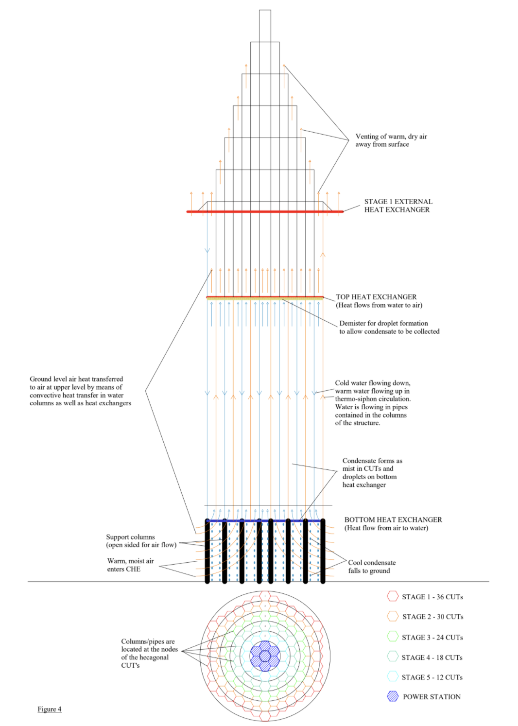
The central two rings in this structure are included for geometric simplicity, but in practice this central space is envisaged to be utilized for the power plant. This plant will be separately described. The water condensate production potential will be dealt with briefly in the next section and details on the benefits for power production can be found in Appendix IV. It must be noted that the heat output from the power station condenser is required in order for the entire system to run. An alternative heat exchanger will have to be located at a heat source (atmospheric or the geo-thermal heat source of power station) in the event of a power station shutdown if water production is required to be continuous.
A point of clarification – note that all that is occurring here is that surface heat is being transferred vertically by means of water to warm air higher up the atmospheric column – this creates a destabilization in the thermal equilibrium of the atmospheric column, resulting in uplift above HXT, with the heavier (cooler) air below being drawn up by the rising air – the designed volumes of the respective air parcels facilitates the net uplift. No energy is being added to the atmospheric column – trapped surface heat is being transferred higher up the atmospheric column by means of an incompressible fluid. A path of lower resistance for convective heat transfer has been established by means of the hydraulic circuit – it is the heat convection through this hydraulic circuit that powers the CHE.
Water Condensate Production #
As mentioned in the background section above, rising air cools, resulting in a reduced capacity to hold water vapor. When the ambient air with a certain humidity is cooled to its dew point, that air is said to be saturated, and is described as being at 100% relative humidity (RH). When it is cooled below that temperature, the water condenses into droplets when the air temperature is above freezing. It may precipitate as snow, hail or frost when temperatures are below freezing. The CHE can be designed to reduce the temperature of ambient air to a target temperature low enough to act as a heat sink for enhanced efficiency during power generation. For the sake of argument, let us nominate -5°C as the target temperature. It is possible to design a CHE for a specific environment with known atmospheric conditions to achieve that final output temperature. The test case analyzed in Appendix III considered relatively dry air of 55% RH at 25°C ground level ambient temperature. The CHE, comprising 120 parallel / series connected CUTs as per Fig. 4, is modeled to produce 437 ML of condensate per day.
Water condensate is formed on the HXB once that HX has reached the dew point of the ambient air. The stage at which this occurs is primarily dependent on the RH of the ambient air. The higher the RH, the earlier the stages reach dew point temperatures. Further cooling occurs during uplift in the CUT after the air has passed through the HXB, resulting in more condensate production in the rising air, typically as fog/mist. A demister placed immediately below HXTwould serve to harvest this condensate from the air stream. So, condensate is harvested by the HXBand the demister just below HXT in the CUTs that operate at or below dew point temperatures.
Conclusion #
The atmosphere has two primary processes of transporting surface heat resulting from solar insolation back out to space – convective uplift coupled with the hydrological cycle (surface evaporation and re-condensation with heat rejection at altitude) and infrared radiation. Infrared radiation is hampered by the changes in atmospheric composition as a result of the increase in CO2 concentration which drives a concomitant increase in atmospheric water content. This proposal offers the potential to reverse this compositional change in the atmosphere by directly reducing the water content of the atmosphere (by enhancing convective uplift), and the return of this water to the biosphere driving increases plant growth, which aids the removal of the CO2 from the atmosphere through increased photosynthetic sequestration.
Alongside the substantial impacts on climate change we can gain the side benefits of relatively concentrated (compared to wind and solar power’s large footprints) renewable and constant power generation as well as an opportunity to change the urban landscape by reversing urban sprawl with a new kind of vertical city – one that generates a surplus of water and power and simultaneously frees up previously unavailable land, allowing for the re-imagining of what a city can be.